
In this article, I am going to explain in detail how to document SSIS packages using Sequence Diagrams and the importance of these diagrams in the field of software engineering, no matter which programming language are you using. In my previous article, I have talked about the various UML Diagrams that are being used to document various software engineering processes. Also, I have talked about modular ETL architecture and how to create such a modular package in SSIS. Sequence diagrams are also a part of the broader UML Diagrams which define the interaction between the various components in the system in a chronological manner.
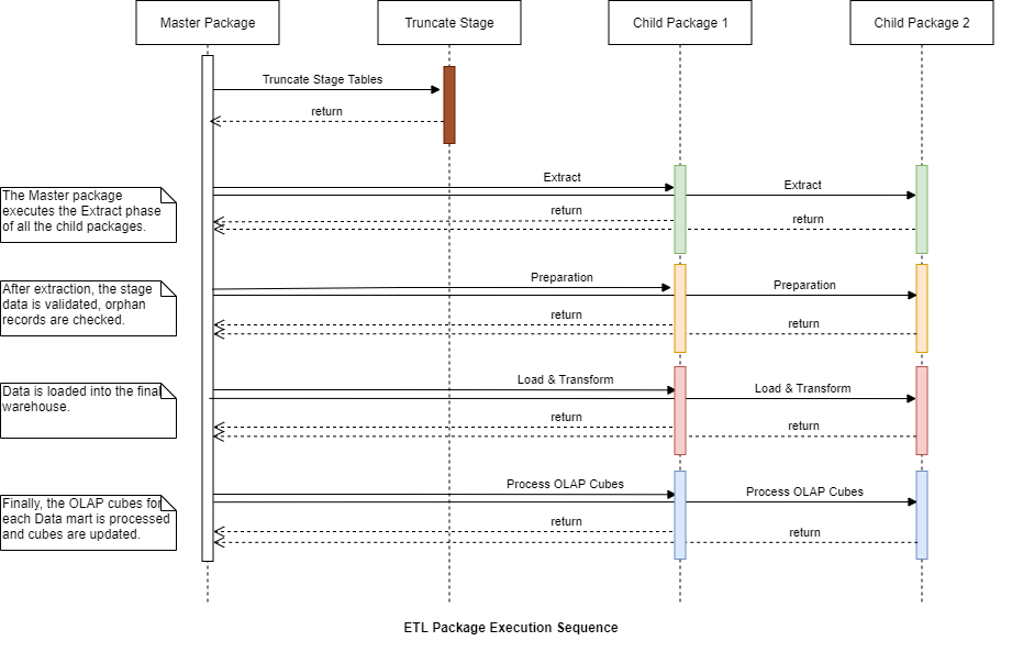
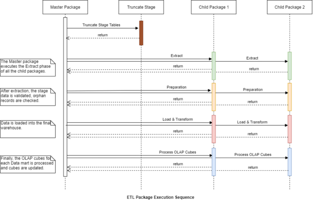
Figure 1 – Documenting SSIS Packages using Sequence Diagrams
As you can see in the figure above, this is how an SSIS package can be documented as a sequence diagram. Although this might look a bit complex in the first step, but if we start with the basics, the concept of drawing such diagrams is simple which we will see later in this article. As explained in the previous article already, the SSIS packages are composed of a single master package that controls the execution of multiple child packages. This is also helpful in controlling which child package would you like to execute or not based on a simple configuration in the master package.
Components of a Sequence Diagram
To begin with, we should have a common understanding of how a sequence diagram is created. At the very basic level, a sequence diagram consists of two dimensions as follows.
- Object Dimension – This is defined by the objects on the horizontal axis. To keep things simpler, the objects are arranged in a way that the ones used earlier are kept on the left and the ones which interact at last are placed on the right. This can be done by placing the individual SSIS packages as objects in the horizontal axis as shown in Figure 1
- Time Dimension – This is the vertical axis which represents the time of action during which the interactions are made and proceeded. This can be the execution time being taken by the SSIS project to complete
These dimensions are plotted in the diagram in the horizontal and the vertical axes and then the objects are added along the horizontal axis. In the case of SSIS packages, the objects can be replaced with child packages which can act as objects when executed from the master package. In addition to these dimensions, few other notations are used in the development of such a diagram.
Actor – An actor is usually a person or an external device or program which has the capacity to initiate or trigger the workflow. These actors are not a part of the internal workflow and can live outside it. In the SSIS packages, this can either be the developer or a DBA, or even a scheduled SQL Agent Job that triggers the ETL process.

Figure 2 – Actor in Sequence Diagram (Source)
Lifeline – A lifeline is the representation of an object in the diagram. It is depicted by using dotted or dashed lines. It is just the extension of the package that is being executed.
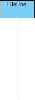
Figure 3 – Lifeline in Sequence Diagram (Source)
Activation – It is the specific duration of time during which the object is activated and stays active during an operation is being performed by it. This can be the duration of execution for the individual phases like extraction, validation, or processing within each SSIS package. In the diagram, these are highlighted by placing small rectangular boxes within the lifeline. If you refer to Figure 1, you can see that the activation boxes are highlighted in colored boxes for each of the phases.
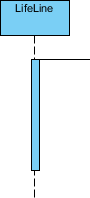
Figure 4 – Activation Box in Sequence Diagrams (Source)
Call Message – A call message is the initiation or start of execution of specific phases within the SSIS package. In the programming world, it can be the methods of the classes which can be used to initiate a specific message call. However, in ETL, it is the initiation of the phases within the package.
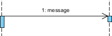
Figure 5 – Call message in Sequence Diagram (Source)
Return Message – A return message is passed from the child package to the parent package with its status such as success or failed, which helps the parent package to decide the execution control flow based on the return package.
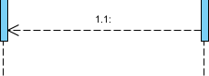
Figure 6 – Return Message in Sequence Diagram (Source)
Creating the Sequence Diagram
Now that we have some idea about what a sequence diagram is all about, let us learn how to create it from scratch. You can use any drawing tool available online like Draw.io or dedicated desktop tools like Microsoft Visio. Either way, you get a fixed set of drawing elements from which you can drag and drop components to a canvas and prepare the diagram. However, there is also a way to programmatically create these sequence diagrams and that is by using Plant UML.
Creating the diagram programmatically has a few advantages over the other techniques. Although PlantUML does not use any programming language to create the diagrams, it uses plain text to construct the commands which can then be stored in a “*.puml” file. This is the extension of the PlantUML file. You can either add this to the SSIS Package repository or store it in an additional location. Personally, I like to keep the files within the SSIS repository which helps me to keep a track of all the changes that have been done.
Let me head over to Visual Studio Code and install the PlantUML extension from the marketplace.
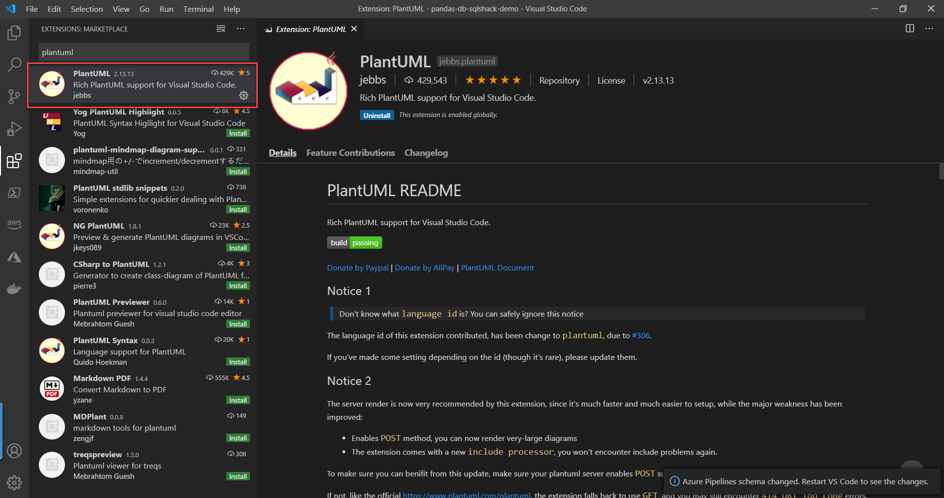
Figure 7 – Installing PlantUML extension for Visual Studio Code
Once the extension is installed, let us go ahead and create a new file in the repository with the name “ssis-sequence-diagram.puml“. Once you are done with creating the file you can go ahead and paste the following code into it.
|
1 2 3 4 5 6 7 8 9 10 11 12 13 14 15 16 17 18 19 20 21 22 23 24 25 26 27 28 29 30 31 32 33 34 35 36 37 38 39 40 41 42 43 44 45 46 47 48 49 50 |
@startuml activate MasterPackage MasterPackage -> TruncateStage : TruncateStageTables TruncateStage --> MasterPackage : return MasterPackage -> ChildPackage1 : Extract activate ChildPackage1 ChildPackage1 --> MasterPackage : return deactivate ChildPackage1 MasterPackage -> ChildPackage2 : Extract activate ChildPackage2 ChildPackage2 --> MasterPackage : return deactivate ChildPackage2 MasterPackage -> ChildPackage1 : Preparation activate ChildPackage1 ChildPackage1 --> MasterPackage : return deactivate ChildPackage1 MasterPackage -> ChildPackage2 : Preparation activate ChildPackage2 ChildPackage2 --> MasterPackage : return deactivate ChildPackage2 MasterPackage -> ChildPackage1 : Load & Transform activate ChildPackage1 ChildPackage1 --> MasterPackage : return deactivate ChildPackage1 MasterPackage -> ChildPackage2 : Load & Transform activate ChildPackage2 ChildPackage2 --> MasterPackage : return deactivate ChildPackage2 MasterPackage -> ChildPackage1 : Process OLAP Cubes activate ChildPackage1 ChildPackage1 --> MasterPackage : return deactivate ChildPackage1 MasterPackage -> ChildPackage2 : Process OLAP Cubes activate ChildPackage2 ChildPackage2 --> MasterPackage : return deactivate ChildPackage2 deactivate MasterPackage |
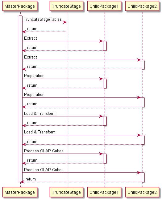
Figure 8 – Documenting SSIS Packages using Plant UML
Save the file and hit “Alt + D” on your keyboard and you should now be able to view a preview of the sequence diagram that we just created. Basically, what this code does is, converts the code that you write and render the visual as you make changes. This is helpful because you make any changes to the diagram just by altering the code. Another advantage is that you can include this file with your source code and add it to the version control. Whenever you need to update to a new version you can use the same file and add your changes. This way you will never lose your documentations and is a good idea to keeps things in check.
Once you are done in creating the diagram, hit “Ctrl + Shift + P” on your keyboard and search for “PlantUML: Export Current Diagram“. Select this option and then select the file format that you want to export to. If you want to store it in a simple file, use PNG or you can choose SVG if you would like to store it in a vector format. Your diagram will be exported to a file successfully.
Conclusion
In this article, I have explained in detail the concept of using Sequence Diagrams. Further, I have also explained how to create these diagrams programmatically using Plant UML as a tool. Using these UML diagrams to document your software is essential because it helps to understand how the workflow of the software behaves when executed. Although these diagrams can be drawn using online drawing tools such as https://draw.io or dedicated tools like Microsoft Visio, it is quite a time-taking and in order to make changes, you need to implement a lot more changes. Using Plant UML, you can automate this and add the diagram within your source code which can be versioned as well.

He is a prolific author, with over 100 articles published on various technical blogs, including his own blog, and a frequent contributor to different technical forums.
In his leisure time, he enjoys amateur photography mostly street imagery and still life. Some glimpses of his work can be found on Instagram. You can also find him on LinkedIn
View all posts by Aveek Das
- Getting started with PostgreSQL on Docker - August 12, 2022
- Getting started with Spatial Data in PostgreSQL - January 13, 2022
- An overview of Power BI Incremental Refresh - December 6, 2021